
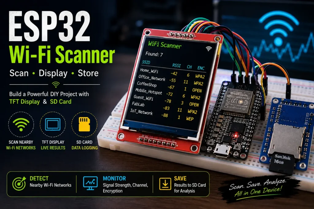
An ESP32 WiFi Scanner is a simple way to explore the wireless networks around you. In this project, I built a portable Wi-Fi scanner using an ESP32, an ST7735 TFT display, and an SD card module.
The ESP32 scans for nearby Wi-Fi networks and collects information such as the SSID, signal strength (RSSI), Wi-Fi channel, and encryption type. The results are displayed on the TFT screen and saved to the SD card for later analysis.
Project Overview
The basic workflow is:
ESP32 → Scan nearby Wi-Fi networks → Display results → Store results on SD card
The ESP32 performs a wireless scan every 10 seconds. For every detected network, the program collects:
- SSID — Wi-Fi network name
- RSSI — received signal strength
- Channel — Wi-Fi channel being used
- Encryption type — such as Open, WPA, or WPA2
The information is then written to a file called:
wifi_scan.txt
This makes the device useful as a small portable wireless-network visibility tool.
Components Used
Hardware
The project uses three primary hardware components:
An SD card is also required for storing the scan results.
SOFTWARE
The project was developed using the Arduino IDE with the following libraries:
WiFi.hSPI.hSD.hAdafruit_GFX.hAdafruit_ST7735.h
The ESP32’s built-in Wi-Fi functionality performs the actual wireless scanning.
How the Project Works
When the ESP32 starts, it initializes the TFT display and SD card.
The screen first displays the project status:
WiFi Scanner
followed by the SD card status.
If the SD card is successfully initialized, the display shows:
SD OK
The ESP32 then switches its Wi-Fi interface into station mode and disconnects from any existing network connection.
After initialization, the scanning process begins.
Step 1 — Start the Scan
The program uses the ESP32 Wi-Fi scanning function:
WiFi.scanNetworks(false, true);
This searches for nearby wireless networks.
The number of networks detected is stored in the variable n.
Step 2 — Collect Network Information
For each discovered network, the program extracts several pieces of information:
String ssid = WiFi.SSID(i);
int rssi = WiFi.RSSI(i);
int channel = WiFi.channel(i);
String enc = encType(WiFi.encryptionType(i));
These values provide a basic picture of the surrounding wireless environment.
For example, a result could look conceptually like:
SSID: Home_WiFi
RSSI: -52
CH: 6
ENC: WPA2
Understanding RSSI
RSSI stands for Received Signal Strength Indicator.
It is generally represented as a negative value in dBm.
For example:
-30 dBm→ very strong signal-50 dBm→ strong signal-70 dBm→ weaker signal-90 dBm→ very weak signal
RSSI can provide an approximate indication of how strong a Wi-Fi signal is at the location where the ESP32 is performing the scan.
However, RSSI should not be treated as an exact measurement of distance because walls, interference, antennas, and environmental conditions can significantly affect it.
Understanding Wi-Fi Channels
The scanner also records the channel used by each detected network.
For example:
CH: 1
CH: 6
CH: 11
This information can be useful when studying wireless network congestion.
If many nearby access points are operating on the same or overlapping channels, wireless interference may become a consideration.
The ESP32 therefore provides a simple way to observe the wireless environment around it.
Detecting Encryption Types
The project also identifies the authentication/encryption mode reported by the ESP32.
The encType() function converts the ESP32’s encryption enumeration into readable text.
For example:
case WIFI_AUTH_OPEN: return "OPEN";
case WIFI_AUTH_WEP: return "WEP";
case WIFI_AUTH_WPA_PSK: return "WPA";
case WIFI_AUTH_WPA2_PSK: return "WPA2";
This allows the output to be easier to understand.
For example:
Network_A | WPA2
Network_B | OPEN
Network_C | WPA/WPA2
From a security-learning perspective, this can help demonstrate the difference between networks that advertise different authentication configurations.
TFT Display
The ST7735 TFT display provides a small visual interface for the scanner.
After completing a scan, the ESP32 displays the number of detected networks:
Found: 7It then displays the available network names and their signal strengths.
For example:
Found: 7

Home_WiFi -45dB
OfficeNet -62dB
Guest_WiFi -71dB
MobileHot -80dB
Because the TFT display is relatively small, only a limited number of results can be displayed at once.
The complete scan information is therefore stored on the SD card.
Storing the Results on an SD Card
One of the most useful parts of the project is persistent logging.
The program opens:
SD.open("/wifi_scan.txt", FILE_APPEND);Using FILE_APPEND means new scan results are added to the existing file rather than replacing previous results.
The program creates sections such as:
----- Scan Start -----

SSID: Home_WiFi | RSSI: -45 | CH: 6 | ENC: WPA2
SSID: OfficeNet | RSSI: -62 | CH: 11 | ENC: WPA2
SSID: Guest_WiFi | RSSI: -71 | CH: 1 | ENC: OPEN

----- Scan End -----
This makes it possible to remove the SD card later and analyze the collected information on a computer.
Automatic Scanning
The scanner waits for 10 seconds after completing each scan:
delay(10000);This means the device continuously repeats the process:
Scan
 ↓
Collect network information
 ↓
Display results
 ↓
Save results
 ↓
Wait 10 seconds
 ↓
Scan again
This creates a simple wireless environment monitoring system.
Important SPI Configuration
Both the TFT display and SD card module communicate with the ESP32 using SPI.
Because multiple SPI devices are being used, each device has its own Chip Select (CS) pin.
In this project:
#define TFT_CS 5
#define SD_CS 21
The program sets both CS pins HIGH initially:
digitalWrite(TFT_CS, HIGH);
digitalWrite(SD_CS, HIGH);
This helps ensure that the two SPI devices do not interfere with each other during initialization and communication.
This was an important part of getting the hardware configuration working reliably.
Complete Code for esp32 wifi scanner
The following Arduino sketch combines Wi-Fi scanning, TFT output, and SD-card logging:
#include <WiFi.h>
#include <SPI.h>
#include <SD.h>
#include <Adafruit_GFX.h>
#include <Adafruit_ST7735.h>

/* ===== DISPLAY ===== */
#define TFT_CS   5
#define TFT_DC   2
#define TFT_RST  4

/* ===== SD ===== */
#define SD_CS    21

Adafruit_ST7735 tft = Adafruit_ST7735(TFT_CS, TFT_DC, TFT_RST);

/* ===== HELPERS ===== */
String encType(wifi_auth_mode_t e) {
  switch (e) {
    case WIFI_AUTH_OPEN: return "OPEN";
    case WIFI_AUTH_WEP: return "WEP";
    case WIFI_AUTH_WPA_PSK: return "WPA";
    case WIFI_AUTH_WPA2_PSK: return "WPA2";
    case WIFI_AUTH_WPA_WPA2_PSK: return "WPA/WPA2";
    case WIFI_AUTH_WPA2_ENTERPRISE: return "WPA2-ENT";
    default: return "UNK";
  }
}

void setup() {
  Serial.begin(115200);
  delay(500);

  pinMode(TFT_CS, OUTPUT);
  pinMode(SD_CS, OUTPUT);

  digitalWrite(TFT_CS, HIGH);
  digitalWrite(SD_CS, HIGH);

  tft.initR(INITR_BLACKTAB);
  tft.setRotation(1);
  tft.fillScreen(ST77XX_BLACK);
  tft.setTextColor(ST77XX_GREEN);
  tft.setTextSize(1);
  tft.setCursor(0, 0);
  tft.println("WiFi Scanner");

  if (!SD.begin(SD_CS, SPI, 1000000)) {
    tft.setTextColor(ST77XX_RED);
    tft.println("SD FAIL");
    while (1);
  }

  tft.println("SD OK");

  WiFi.mode(WIFI_STA);
  WiFi.disconnect(true);
  delay(500);
}

void loop() {
  tft.fillScreen(ST77XX_BLACK);
  tft.setCursor(0, 0);
  tft.setTextColor(ST77XX_GREEN);
  tft.println("Scanning...");

  int n = WiFi.scanNetworks(false, true);

  File logFile = SD.open("/wifi_scan.txt", FILE_APPEND);

  if (logFile) {
    logFile.println("----- Scan Start -----");
  }

  tft.fillScreen(ST77XX_BLACK);
  tft.setCursor(0, 0);
  tft.println("Found: " + String(n));

  int y = 15;

  for (int i = 0; i < n; i++) {

    String ssid = WiFi.SSID(i);
    int rssi = WiFi.RSSI(i);
    int channel = WiFi.channel(i);
    String enc = encType(WiFi.encryptionType(i));

    if (y < 120) {
      tft.setCursor(0, y);
      tft.print(ssid);
      tft.print(" ");
      tft.print(rssi);
      tft.print("dB");
      y += 10;
    }

    if (logFile) {
      logFile.print("SSID: ");
      logFile.print(ssid);
      logFile.print(" | RSSI: ");
      logFile.print(rssi);
      logFile.print(" | CH: ");
      logFile.print(channel);
      logFile.print(" | ENC: ");
      logFile.println(enc);
    }
  }

  if (logFile) {
    logFile.println("----- Scan End -----\n");
    logFile.close();
  }

  WiFi.scanDelete();

  delay(10000);
}
What I Learned From the ESP32 WiFi Scanner Project
This project helped me understand several concepts beyond simply writing an ESP32 program.
1. ESP32 Wi-Fi capabilities
I learned how the ESP32 can scan for wireless networks without connecting to them.
2. SPI communication
The project required using SPI for both the TFT display and SD card.
Managing separate Chip Select pins helped me understand how multiple SPI peripherals can coexist on the same microcontroller.
3. Data logging
Instead of only displaying information temporarily, I learned how to store scan results persistently on an SD card.
4. Embedded-system debugging
Getting the display, SD card, and ESP32 working together required troubleshooting hardware connections, initialization, and SPI communication.
5. Wireless security visibility
The project also introduced me to practical concepts such as SSIDs, RSSI, Wi-Fi channels, and wireless authentication modes.